Switching via phone call
SIP Ring Switch on Asterisk telephone system
Voice-over-IP access is now replacing analog telephone connections. This has had the effect of melding telephony and network technology. Even mature PBX systems no longer take up entire rooms, but rather run on normal PCs and even on embedded systems like Raspberry Pi. This is made possible for example by software packages such as the Open Source Project Asterisk and SIP protocol (Session Initiation Protocol).
The SIP Ring Switch can be connected to the telephone system over the local network just like a VoIP telephone - just that the SIP Ring Switch does not open a voice connection when a call comes in , but rather initiates a switching action.
Step 1 - Connect the SIP Ring Switch
Wiring
To operate the SIP Ring Switch a supply voltage of between 12V and 24 VDC or a corresponding power supply is required.
The connected supply voltage is switched to the corresponding output terminal in the ON state.
If a potential-free contact is required for control, e.g. if the bell is operated with an AC voltage, a coupling relay can be inserted.
Wiring of the SIP Ring Switch should be performed only by trained persons.
For Output 0 for example to Terminal 4, with the associated ground on Terminal 5.
Network
The SIP Ring Switch must be connected to a free LAN terminal on the Fritzbox.
Step 2 - Configure network
For the Asterisk telephone system to be accessed reliably, the SIP Ring Switch should always have a static IP address assigned.
In networks where IP addresses are assigned by DHCP, the address must be either fixed assigned in the DHCP system or lie in an IP range which is excluded from DHCP address assignment.
To assign the SIP Ring Switch a static IP address, use a Windows PC to start the
WuTility tool.

Click on the IP address icon to start the dialog for IP address assignment. Enter here the desired IP address and click on the Next button.
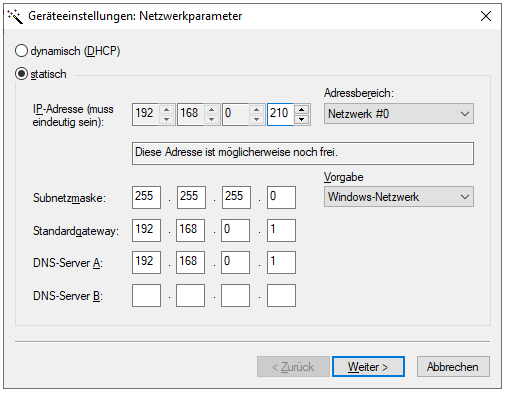
The SIP Ring Switch can now be reached at the assigned address.
Step 3 - Set up an extension in the Asterisk telephone system
For the SIP Ring Switch to be able to switch using a call number, there must be an extension created and configured in the telephone system for each desired switching action.
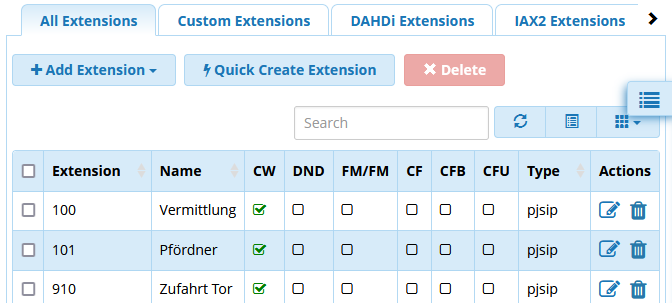
In the menu branch Applications select Extensions. Here click on the + Add Extension and there set up a new extension for the desired switching action.
Step 4 - Configuring the SIP Ring Switch
SIP basic settings
Now the SIP Ring Switch must be configured for registering on the Asterisk telephone system. Log in as Administrator on the web interface of the SIP Ring Switch and select Communications paths>>SIP.
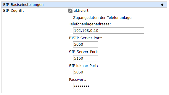
Under SIP basic settings enable SIP access and enter the access data for your Asterisk telephone system. For Password the password for the extension must be entered. Then confirm by clicking on the Apply button.
Extension inventory
To add a new extension to be represented by the SIP Ring Switch, click on the Add button.
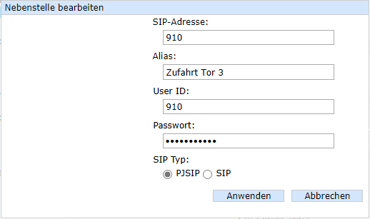
The SIP address is entered using the following syntax:
<User name>@<IP address of the telephone system>
For SIP type the SIP procedure used by the telephone system must be selected. Confirm you entries with Apply so that they can be entered in the inventory list.

caller inventory
To prevent random or unauthorized calls to trigger switching events, callers can be listed in the caller inventory who have permission to access the SIP Ring Switch.
There are two ways to do this:
Learn new call numbers
Click on the Scan button.

Click on Start and then call the associated extension.
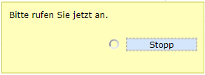
The SIP Ring Switch uses Scan mode to collect the SIP addresses for all incoming calls until you click on Stop.
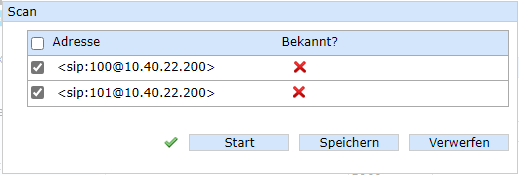
Highlight the SIP addresses you with to add to the caller inventory.
Add new call numbers by entering
To manually enter an SIP address, click on the Add button.
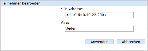
Enter the desired SIP address. Syntax is important here:
<sip:Call number@IP of the telephone system>
Using "*" as a wildcard enables any desired number to be allowed. After clicking on Apply the SIP address is added to the inventory list.

Clicking on the Edit button allows you to modify the entries, for example to assign a meaningful alias name.
Configure output for pulses
Commonly used barrier controllers require a brief control pulse for opening and closing. To have an output reset automatically, for example 2 seconds after activation, it must be configured for Pulse mode.
In the SIP Ring Switch configuration select Basic settings>>Outputs and for the desired output Advanced Settings. There enable Pulse Mode and for pulse duration enter 2000 ms.
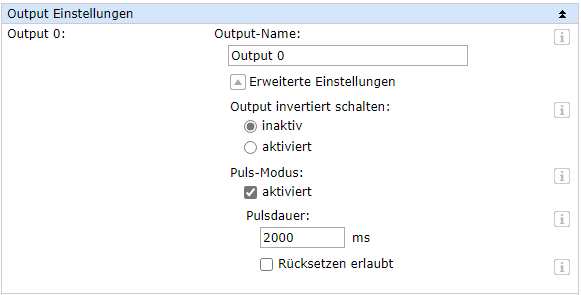
Set up switching action
Now you must specify which output should switch when a call comes in on which extension. In the menu tree click on Actions and then on the Add button.
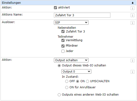
As the trigger select SIP. Select the extension to be used for triggering the action when a call is made. In the inventory list determine who should switch via call. Finally, select as initiator Switch Output > Switch output on this Web-IO and then the output to be switched. As switching state ON must be enabled.
After confirming by clicking on the Apply button the SIP Ring Switch is ready for switching.
