Access via TCP/UDP
Access via TCP
Similar to a telephone conversation, TCP requires that first a connection be opened before information can be exchanged.
The client opens the connection, which is then received by the server. In applications for Web-IO with binary sockets the Web-IO can operated either as server or client depending on the configuration. In most cases the application assumes the role of the client and the Web-IO is the server.
The Web-IO as server
When used as a server the Web-IO has a TCP port open for receiving connections (port 49153 unless otherwise configured). The client, i.e. the application, opens a connection to the IP address of the server on this port. The client also opens a TCP port (dynamically changing) on which it can receive data from the server, i.e. the Web-IO.
As soon as the connection is open, the application can send data to the Web-IO (Request), which are then replied to by the Web-IO (Reply). If so configured the Web-IO can report the status of the inputs (Event Message) without a request by the application.
The application generally handles closing of the TCP connection. The Web-IO closes the connection only in case of errors.
In TCP binary socket mode the Web-IO can at the same time receive exactly one connection on the opened TCP port. Any attempt to open a connection from another client is rejected (similar to a busy telephone).
The Web-IO as client
When used as a client the Web-IO handles opening the connection. Triggered by a signal change on the inputs, the connection to a preconfigured server is opened.
As soon as the connection is open, the status of the inputs is transmitted. As long as the connection is open, data can be exchanged just as if the Web-IO were being used as a server.
Opening the connection is triggered by an Inactivity Timeout, i.e. a time limit. If during the set time there is no change on the inputs, the Web-IO closes the connection.
Access via UDP
Unlike a telephone conversation, with UDP there is no connection. Similar to radiotelephony the information is simply sent. UDP uses no client and server, rather what are called UDP peers which are all equally permitted to send their datagrams.
The application sends data to the Web-IO (Request) to which the Web-IO responds accordingly and if necessary sends an answer (Reply). In addition, if correspondingly configured the Web-IO sends a datagram when the status of the inputs changes.
Configuring Web-IO
Configuring Web-IO for binary access
From the menu tree in the web interface, select Communication channels >> Socket API and enable Binary1 sockets. The remaining configuration depends on which type of socket access is needed.
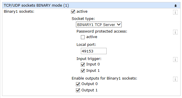
Web-IO as binary server For Socket Type select BINARY1 TCP server.

The local port can if necessary be adapted to your own application.
If the Web-IO needs to automatically send the status to the application when the inputs change, check the corresponding boxes under Input Trigger.
In addition, outputs which need to be switched by the application must be enabled.
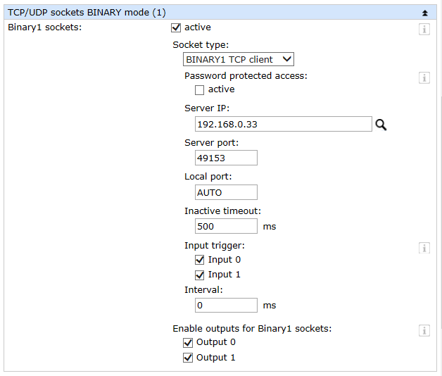
Web-IO as binary client For Socket Type select BINARY1 TCP client.

For Server-IP enter the IP address of the network device on which the server application used for connecting the Web-IO is active.
The Server Port is the port on which the server application receives the connection. This port can be adjusted if needed.
The local port should in normal usage remain set to AUTO so that it is dynamically assigned. If the infrastructure requires it, a specific port may however be entered.
Inputs which should trigger opening of a connection when the status changes must be enabled under Input Trigger. Once there is a connection, the status conditions are automatically sent to the application.
You may use the Interval field to specify whether and at what intervals a connection should be opened.
Finally, outputs which need to be switched by the server application must be enabled.
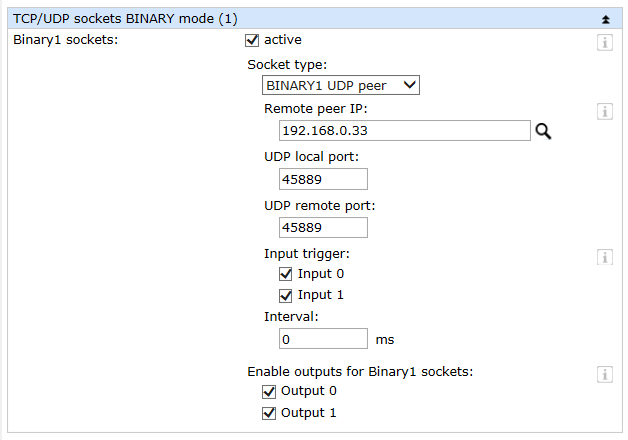
Web-IO as binary UDP peer For Socket Type select BINARY1 UDP peer.

For Remote-Peer-IP enter the IP address of the network device to which the Web-IO datagrams should be sent.
UDP local port and UDP remote port can if needed by adjusted to your own application.
If the Web-IO needs to automatically send the status to the application when the inputs change, check the corresponding boxes under Input Trigger.
You may use the Interval field to specify whether and at what intervals datagrams should be sent to the application.
Outputs which need to be switched by the application must be correspondingly enabled.
Binary structures
Composition and structure of the binary structures
Regardless of whether TCP or UDP is used for accessing, the structures which are exchanged remain the same.
Data structures are individual variables which are stored in memory one after the other as a byte sequence. In this arrangement they are also sent over the network. All binary structures for the Web-IO consist of four 16-bit values which can be followed by 8-, 16- or 32-bit values depending on the task of the structure.
The structure I/O driver
Start_1 and Start_2 These two 16-bit variables always have a value of 0 and as a start sequence represent the start of each structure.
StructType The structure type encodes what the Web-IO should do and to what its reply refers. Structures of a particular type have a type-specific structure.
StructLength Indicates the total length of a structure in bytes.
What at first glance may seem complicated actually represents a great advantage: particular information is always in the same location within the structure where it can be immediately found. This means that parsing of character strings for certain contents is not necessary.
Example: Querying inputs and outputs
In the following example we will show you how to query the status of the inputs and outputs and how the corresponding reply from the Web-IO is constructed.
Structure type RegisterRequest The RegisterRequest structure corresponds to the makeup of the basic structure I/O driver. For StructType insert 0x21 hex (dec 33) and set StructLength to 8 (bytes).
The structure type RegisterState In reply the Web-IO sends a type RegisterState structure.
In the case of RegisterState structure the first part corresponds to the basic structure I/O driver. For StructType insert 0x31 hex (dec 49) and set StructLength to 0x0E hex (dec 14 bytes).
This is followed by three more 16-bit variables. The variable DriverID actually no longer has any meaning, but remains a component of the structure having a value of 2 for reasons of compatibility with older Web-IO models.
The variables InputValue and OutputValue indicate the switching states of the inputs and outputs. The entered value corresponds to the bit pattern of the inputs and outputs. The coding is simple - here is an example for the 12 inputs of a Web-IO model #57730:
Inputs 0, 1, 5, 7, 10 and 11 are ON. The other inputs are in the OFF state.
And so here 1100 1010 0011. In hex this corresponds to 0xCA3 or decimal 3235.
In the example above the value for OutputValue is 1, so that only Output 0 is ON. All other outputs are in the OFF state.
A detailed description for communication with binary structures can be found in the binary brief overview or in the programming manual for the Web-IO.


