Application for rule.box:
An example in detail
Correct use of Node-RED

You activate the video function using the following button, whereby you use the provider Google and (at your own risk in terms of data protection ;) share data with it.
We would like to make you more familiar with how to work with Node-RED. Take a look at the video shown here or read the description on this page, in which we give you an overview of the editor areas and explain the example flow pre-installed on the rule.box step-by-step.
What you’ll need:
No problem: We will be glad to provide you with a rule.box for 30 days at no charge. Simply fill out the sample order and we will send the rule.box for testing on open account. If you return the device within 30 days we will fully credit the invoice.
To sample ordersWhat’s explained:
- Orientation in Node-RED Editor - The nodes
- Orientation in Node-RED Editor - The workspace
- Orientation in Node-RED Editor - The Info column
- Creating an example flow

1. Orientation in the Node-RED Editor - The nodes
-
You reach the Node-RED Editor through the corresponding link on the overview page of your rule.box.
-
In the left section of the editor you will find a list with installed nodes. These are subdivided into categories according to their functions.
-
If you move the mouse over a node you will see a short description of its function.

-
To use a node, simply drag it to your workspace.
-
Double-clicking on the node lets you configure it. The text in the "Name" field names and identifies the node on the workspace. Under "Topic" you can find additional information which the node can include when sending.
-
Depending on the type of node many other properties can be configured.
2. Orientation in the Node-RED Editor - The workspace
-
The workspace is located in the center of the Node-RED editor where you create your flows.
-
New flows can be added using the plus symbol in the upper right corner of the workspace.
-
The list symbol to the right of it lets you display an overview of the available flows.
3. Orientation in the Node-RED Editor: The Info column
-
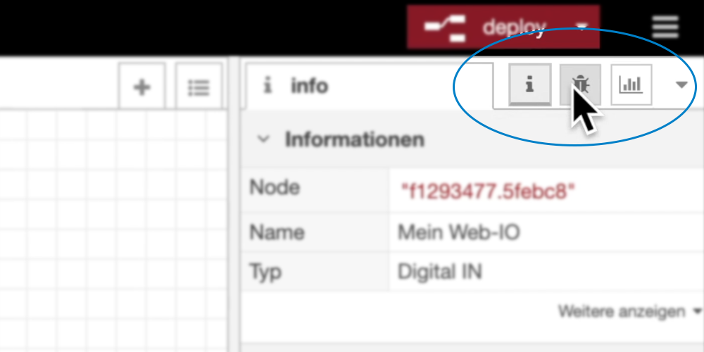
The information column on the right side shows you information for the elements you selected depending on the work step.
-
In addition the column includes two additional symbols.
-
The debug output can point you to possible errors or problems.
-
Next to it you will find an overview of the layout of your dashboard. If you wish to use visualization elements for your flow, you can specify here how and whereyour flow should be displayed in the dashboard.
4. Create the example flow
-
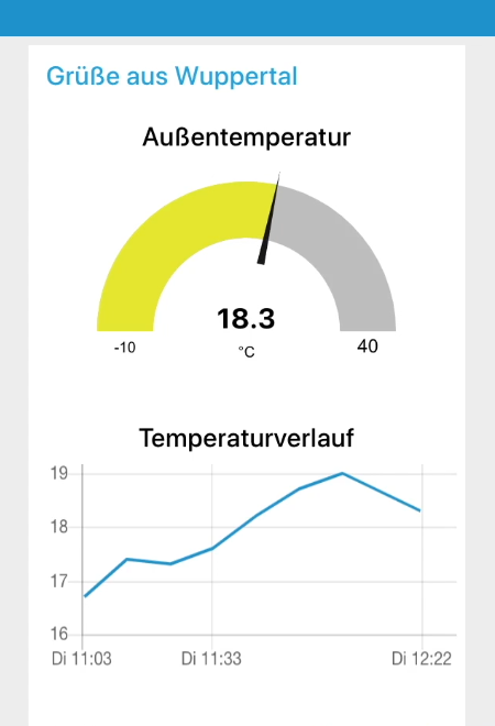
The rule.box has a factory installed flow which uses a Web Thermometer to show the outside temperature at the W&T headquarters building in Wuppertal.

-
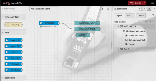
First the nodes required for this application - "Analog IN", "gauge", "chart" and "text" - were added to the workspace and configured accordingly in the following.
-
The output of the "Analog IN" node was wired to the inputs of the "gauge" and the "chart" nodes to enable a correct output of the temperature on the dashboard.
-
Use deploy to confirm and implement flows you have created.
-
You can also reach the dashboard through the overview page of your rule.box. There you can read the current temperature.