Background information:
RS422 Interface
RS422 interfaces were developed for serial high-speed data transmission over great distances and are increasingly used in industrial applications. A maximum of ten RS422 devices can be connected in parallel with a sender within a transmission direction.
Signals and Connectors
No mechanical specification exists in the RS422 standard. Instead, reference is simply made to RS449, which describes a 37-pin SUB-D connector. Cost and space considerations however have prevented this connector style from becoming widely accepted. Instead, 9-, 15- and 25-pin SUB-D connectors are mainly used. There is no uniform pin configuration, so that the pinouts described in the documentation must always be consulted when connecting RS422 devices.
Physical Transmission Procedure
The serial data are transmitted without a ground reference as a voltage differential between two corresponding lines. There is a conductor pair for each transmitted signal consisting of an inverted and a non-inverted signal line. The inverted line is generally indicated by the index "A" or "-", with the non-inverted line designated as "B" or "+". The receiver simply evaluates the difference between the two lines, so that common mode noise of up to 7V on the transmission line will not result in a falsifying of the actual signal. RS422 senders under load provide output levels of +/-2V between the two outputs; the receive chips still recognize levels of +/-200mV as a valid signal.
The assigning of differential voltage to a logical state is defined as follows:
A - B < -0.3V = MARK = OFF = logical 1
A - B > +0.3V = SPACE = ON = logical 0
Cable length
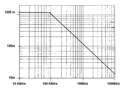
The attainable cable length depends on the baud rate used and is according to RS422 standard a maximum of 1200 meters at baud rates below 100 Kbit/s.

Through use of the symmetrical transmission procedure in combination with low-capacitance and low-attenuation, twisted-pair cables, extremely reliable connections over long distances at high transmission rates can be achieved. The use of high-quality TP cable prevents on the one hand side-to-side crosstalk between the transmitted signals while on the other hand reducing the sensitivity of the transmission device to induced noise signals.
Terminating
The use of a terminator on the cable ends is specified in the standard as a function of the application.
At transmission speeds greater than 200 kbps or a group delay time on the cable of more than a half bit time (for NRZ coding), reflections should be suppressed by using a terminator corresponding to the cable impedance. For twisted-pair cables, this value generally lies in a range between 100 and 200 Ohms.
Special Features
Although designed for long distances, between which potential shifts are generally unavoidable, the standard for RS422 interfaces does not prescribe galvanic isolation. Since the receiver chips are sensitive to a shift in ground potentials, galvanic isolation is a must for reliable installations.
When installing, you must observe correct polarity of the conductor pairs, since incorrect polarity will result in inversion of the data and handshake signals.