RS485 Bus Systems
Physical transmission processes, cable length, polarity and measurements
Basics
The RS485 interface is, like the RS422 interface, intended for serial high-speed data transmission over long distances. In the area of industrial automation the RS485 interface is still very widely used and is only slowly being replaced by Ethernet-based interfaces.
Whereas RS422 only allows uni-directional connection of up to 10 receivers to one driver. RS485 is designed as a bi-directional bus system with up to 32 drivers and receivers. With modern transceiver ICs, reducing the load on the connection caused by the bus node makes it possible to use up to 128 drivers and receivers on one bus system.
The physical differences between RS422 and RS485 interfaces are inconsequential, so that the same transceivers can be used for both interfaces.
Since multiple drivers operate on a common line, a protocol must be employed to ensure that no more than one data sender is active at a time. All drivers must at this time be in a high-resistance state.
The RS485 standard only defines the electrical specifications for differential receivers and senders in digital bus systems. ISO 8482 standardizes in addition the cabling topology with a maximum length of 500 meters.
Terminal devices with no RS485 terminal can be easily retrofitted with an RS485 interface in various ways depending on the existing interfaces:
Product overviews
Construction
An RS485 bus can basically be constructed as a 2-wire or 4-wire system.
RS485 2-wire bus
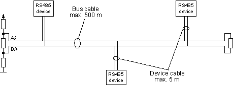
The RS485 2-wire bus consists as shown in the diagram below of the actual bus cable with a max. length of 500 m. The devices are connected to this cable through a stub cable of max. 5 meters. The advantage of 2-wire technology lies essentially in the multi-master capability, whereby each device can in principle exchange data with any other device.
The 2-wire bus is essentially only half-duplex capable. This means that since only one transmission direction is available, only one device can send data. Only after end transmission is completed can other devices reply. The best-known example of 2-wire technology is PROFIBUS.

RS485 4-wire bus
The 4-wire technique used by DIN Measurement Bus (DIN 66 348) for example can only be used by master/slave applications. As the drawing shows, the data output on the master is wired to the data inputs of all the slaves. The slave data outputs come together on the data input of the master.

Physical Transmission Procedure
As in the case of RS422 interfaces, the serial data are transmitted without a ground reference as a voltage differential between two corresponding lines. Each transmitted signal has a conductor pair consisting of an inverted and non-inverted signal line. The inverted line is generally indicated by the index "A" or "-", with the non-inverted line designated as "B" or "+".
The receiver simply evaluates the difference between the two lines, so that common mode noise on the transmission line will not result in a falsifying of the actual signal.
RS485 senders under load provide output levels of +/-2V between the two outputs; the receive chips still recognize levels of +/-200mV as a valid signal.
The association of differential voltage levels to a logical state is defined as follows:
A - B < -0.3V = MARK = OFF = logical 1
A - B > +0.3V = SPACE = ON = logical 0
Cable length
Through use of a symmetrical transmission procedure in combination with low-capacitance and low-attenuation, twisted-pair cables, extremely reliable connections over long distances at high transmission rates can be achieved over a distance of up to 500 m.
The use of high-quality TP cable prevents on the one hand side-to-side crosstalk between the transmitted signals while on the other hand reducing the sensitivity of the transmission device to induced noise signals.
A cable terminator with termination networks is always required for RS485 connections in order to force the quiescent level on the bus systems at the times when no data sender is active.
Galvanic isolation
Although designed for long distances, between which potential shifts are generally unavoidable, the standard for RS485 interfaces does not directly prescribe galvanic isolation. But since the receiver chips are sensitive to a shift in the ground potentials, reliable installations strongly dictate that galvanic isolation as defined in ISO 9549 be implemented.
Polarity of the wire pairs
When installing, you must observe correct polarity of the conductor pairs, since incorrect polarity will result in inversion of the data and handshake signals. Especially when there are difficulties with the installation of new terminal devices, any troubleshooting should start by checking the bus polarity.
Measurements on bus systems
Difference measurements (measuring Bus A vs. B), especially with an oscilloscope, can only be made using a test instrument galvanically isolated from the ground potential. Many manufacturers place the reference point of the measuring input to ground, which can result in a short circuit when measuring on an RS485 bus.


